Assembled mesh generation

Hi,
I needed to generate a volume mesh starting from a surface with some “imprinted” curves.
This surface is the upper surface of a slab and the curves define areas with different loads. These areas have to be used in FLAC3D to define face groups to make it possible to assign quickly specific loads.
In the other horizontal slab surface (the lower one) I didn’t want to have such curves to simplify as much as possible the mesh.
I followed the procedure I’m sharing with you and I would like to know if someone can check its correctness:

  1. with NonmanifoldMerge, generation of a single surface (upper surface) starting from the surfaces defined by the curves.

  2. with Mesh, generation of a single mesh for the whole upper surface.

  3. with ExtractMeshEdges, extraction of all the edges of the previously generated mesh.

  4. with GSurf, remeshing the mesh selecting also the extracted edges. In this way, the mesh generated by Griddle fits the internal curves.

  5. generation of the other slab faces and use of NonmanifoldMerge for such faces.

  6. with Mesh, generation of the mesh of the other slab faces. The two meshes are not conformal.


  7. with GInt, make the two meshes conformal.

  8. use DupBorder, to extract the border of the mesh of the upper surface.

  9. use GSurf to remesh the second mesh with Griddle, selectin also the border. The two meshes generated with GSurf are conformal.


  10. use GVol to generate the volume mesh. I obtained the following error message with naked edges highlighted in yellow in the second picture. Is it normal?

  1. importing the mesh in FLAC3D. Is there a way within FLAC to check if the grid is fully conformal?

1 Like

Maybe you can just extrude the curves along the normal of the plane that contains them and then cap the surface. Next, generate de mesh as usual. You should have zone groups but surfaces will be discretized as well.

Hi, Francesco,

Overall, the procedure that you described makes sense and you can continue using it. Below are replies to your questions:

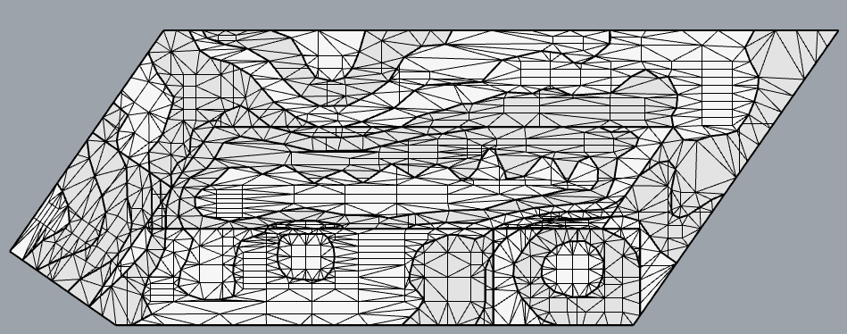
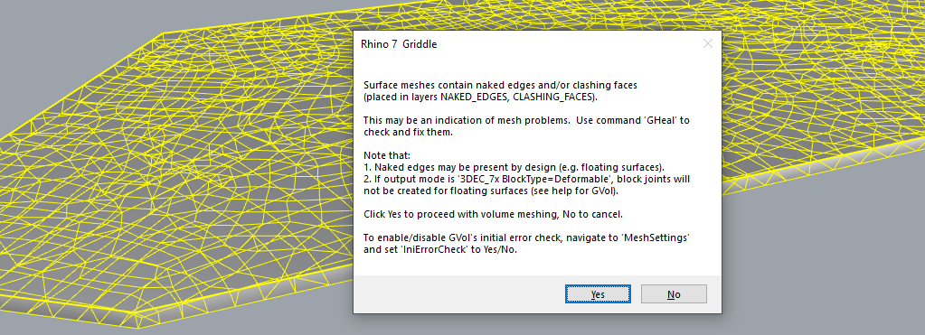
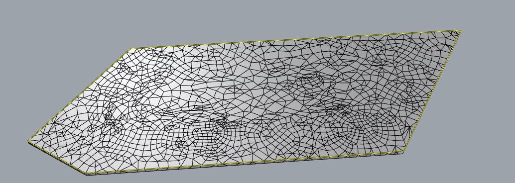
10: Seeing the message about Naked edges is normal. Before GVol starts working on volume meshes, it checks for the presence of free surface mesh boundaries or edges (in general, they are called naked edges). Let’s consider a simple mesh cube with each side represented by a planar face; there are no naked (free) edges in it - each side is fully connected to the other side and this cube creates a watertight (close-volume) domain which can be filled with volume mesh. Now, if you remove one side or cut a hole, the cube becomes non-watertight, and it cannot be filled with volume mesh. In this case, the check will indicate that there are naked edges, and they have to be fixed before volume meshing. However, if you only extract one side of the cube to make a separate mesh out of it (consisting of one quad face) but not delete it, free/naked borders will appear, but the domain still stays watertight and valid: now it just consists of two conformal meshes. This is what happens in your case, and you can ignore the message.
This message is intended for people to pay extra attention to the presence of naked edges in the model, but they can be there by design or because of some problems (e.g., holes, non-conformal intersections, etc.) You can turn off this check and message by going to GVol -> MeshSettings -> IniErrorCheck -> set to 'No'.

11: First of all, GVol is a conformal volume mesher, it will not operate or create non-conformal meshes. However, the simplest way to check if FLAC3D mesh is conformal is to run couple commands and check their output:

  • zone gp merge - merge coincident gps, if there are any. If you work with a single mesh, the command should output 0 gps merged.
  • zone attach by-face - attach all non-conformal faces (which includes edges and gps). If you get that 0 faces are attached, it means that the mesh is fully conformal. This may be useful to check when you already have a model in FLAC3D and you add another conformal piece to it.

One thing that I may suggest is using GExtrude command instead of steps 5-9. The command extrudes mesh boundaries to a predefined surface (in your case, create a large plane at desired position) and it keeps extruded mesh conformal with the original mesh. You can also specify some of the meshing parameters in the command (however, if you keep extruded part separate, you can always remesh it). See help documentation about the command and Tutorial 6, where it is used.


Note that GExtrude may not work well if the extruded mesh has “foldover” (Z-type) boundary in the extrusion direction.

An approach that Gian has offered, is also valid, but as you have separate meshes generated from each curve, you will have to use GInt to intersect them. The good thing about this approach is that it would create separate groups.

Finally, if you work with planar surfaces, you may consider using FLAC3D Extruder to generate a slab. You will need to import a DXF into it, discretize edges as desired, create unstructured meshes for all 2D domains, and then extrude model in 3rd direction (you can specify the direction). The plus of this approach is that generated zones will be of hexahedral and wedge types only (which are higher quality), the minus - is that it may be a bit tricky to achieve desired discretization of the edges in 2D plane (it will depend on the initial DXF).

In general, there are numerous ways to create meshes for FLAC3D and you may consider using one approach or another depending on complexity of the mesh and time available for creating it.

Dear Andrey,
thank you very much for your reply.
I have one additional question about the use of Gint to make the meshes conformal.
In the video Generate a Hybrid Mesh by Combining Block Ranger and GVol to obtain conformal mesh between the domain and the outer tunnel mesh the steps are as follows:

  1. meshing the domain
  2. use GInt to make the mesh conformal (only the mesh of the domain is modified)
  3. use GSurf to remesh the domain mesh selecting also the tunnel borders as hard edges
  4. use GVol to generate the volume mesh

I found that, sometimes, GInt modifies also the “base” mesh (in the case of the video the tunnel mesh) and I didn’t understand which is the parameter that set this behavior. This way to work is tedious because it modifies also previous defined meshes. In these cases, I use directly GSerf selecting also mesh borders without the use of GInt before. Is it correct to skip GInt is such cases? There is a way to avoid GInt to modify the mesh already defined?
Thank in in advance.

Thank you Gian for your reply.

@Francesco_IT These are good questions. Let me make few points here:

  • GInt internally uses an algorithm that requires input meshes to contain triangular elements only. Thus, if you intersect quad or quad-dominant meshes, quads are split into 2 triangles. After that GInt intersects triangular faces where needed. So, GInt doesn’t fully change the structure of the mesh (topology stays the same) but it becomes triangular mesh. We realize that it is a limitation of the algorithm and for the next version of Griddle we plan to develop more robust algorithm that preserves not intersected mesh faces or parts. Right now there is an option to convert output triangular mesh into quad-dominant, but this option randomly picks two neighboring triangles and creates a quad; thus output quads may differ from input quads (this is mostly to reduce number of mesh faces).

  • It is important to intersect surface meshes before doing remeshing; in this case, conformity is preserved by GSurf. Otherwise, not properly intersected meshes will be remeshed separately and conformity may be lost.

  • In the video, as far as I remember, it is actually not necessary to do mesh intersection between the tunnel and box. But this is only due to the specific discretization of the tunnel boundaries: each segment of the boundary polyline is an edge of a face. In more general case, e.g., when you have smaller faces, intersection is needed.

  • For the example in the video, you can create a copy of a tunnel and intersect it with the box - this way box faces will adjust (become conformal) to the tunnel faces at the boundary. Then delete the tunnel copy (as the mesh becomes triangular) and restore the original tunnel mesh. This approach works due to the discretization of the tunnel boundary (as tunnel mesh is not intersected, it is only triangulated).

  • A more useful approach to preserve one mesh (1) when intersecting with another (2) is like this.
    Before intersecting, extract copies of mesh nodes from mesh 1 (_ExtractPt). Select both meshes and intersect them (_GInt). Select meshes and points and remesh them (_GSurf). Points will serve as hard nodes and GSurf will create nodes at those locations in the output mesh. Note this approach works only if GSurf’s MinEdgeLength is greater than typical face size in mesh 1 (otherwise GSurf may insert additional faces between extracted nodes. Below is an example.

In general, if you work with analytical surfaces (e.g. BReps, Nurbs) you can merge them together using _NonManifoldMerge. Then mesh them with _Mesh command which will create initially conformal but rough meshes. After that you can remesh with GSurf and skip GInt completely (see Tutorial Example 3). However, when engineers work with complex geological meshes that initially are very rough and not conformal, mesh intersection is almost always needed.

Dear Andrey,
thank you very much for the clear explanation.
Now, I understand better how the things work with GInt and GSurf and why sometimes it happens that the first mesh is not modified (i.e. each segment of the boundary polyline is an edge of a face).
Also, your tip in the last point will be very helpful in future for me, in fact, as often I have to manage very complex geometries, the “global” approach with one “closed non-manifold polysurface” obtained with NonManifoldMerge produces several meshing errors which cannot be solved with Gheal, also using hyperlinks for size control for each polysurface. So, I have to mesh blocks of polysurfaces separately.
Very helpful forum!

1 Like