We are developing a 3D model of a slender excavation with retaining walls, and under some circumstances have found that intersecting liners exhibit bugs in the coupling stresses, leading us to try modeling the retaining walls using zones.
However, we suspect the resulting deformations to be underestimated based on some 2D analyses performed using liners. The question is whether there are known issues regarding the bending stiffness of zones. We are using large-strain.
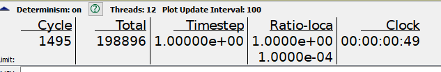
Another issue we are encountering is a ratio-local that does not decrease below 1 despite deformations having stabilized:
This is presumably associated with changes in the mesh near the corners where convergence is high:
although one would not expect that this affect the deformation far away from the corners, correct? or is this definitely something that must be dealt with and avoid at all cost?
Dear {juantello}, This is David Potyondy. I am the developer of the structural element logic. Here are a few points. (1) The bending behavior of zones is very poor: they are much too stiff unless a large number of zones is used through the thickness. To model such a thin shell structure well, you should use a liner. (2) I have been in discussion with Derrick Blanksma about the possible bug in the behavior of a liner that has a 90-degree bend. There is an Itascan who does much modeling with liners, and he has seen a similar behavior. He believes that the effect is local to the corner, and that the overall liner response away from that corner is correct. Nonetheless, I will look into this issue. To do so effectively, I need more information about what it is that you are modeling. I suggest that we go offline, and begin to correspond directly via email. Please send me an email at {dpotyondy@itascacg.com}.
2 Likes
Dear {juantello}, This is David Potyondy. I have carefully examined the “liner corner issue”. The code is working fine, and the responses are continuous and correct across any 90-degree corners. There is no need to perform complex link-attachment changes to the model; instead, all works fine just using the {struct liner create by-zone-face separate} command. All of this is explained in the attached slide set. You are modeling the excavation of a pit supported by retaining walls. As you will see, the test cases have confirmed that such a problem can be modeled easily using either a standard (one-sided) or embedded (two-sided) liner. The reason for the “dip” in values of normal stress when you cross a corner is explained in slide 25 of the attached slide set.
Not sure how to attach a slide set. . .stay tuned.
Hi David,
Thank you for your reply. I will implement this in the code. It means a lot that you take the time to address these issues.
Cheers
Here is the pdf @dpotyondy refers to.
LinerCorner.pdf (6.8 MB)
Dear juantello, If you would like to see the project files and data files, just let me know.
Dear David, thank you for your attention.
I think I solve the issue of normal coupling stresses, trusting that they are ok as per your last email even though they don’t look great at the corner (note that we haven’t been joining nodes in the discussion thus far, but this is necessary), and it might be causing some strange visualization:
However, other than this, the behavior seems ok.
What I’m having trouble doing is extracting the moment in the liner:
as I get a message saying the elements are invalid. Any idea why this might happen?
Thank you in advance,
I’ve attached the files FYI.
(Attachment fishtank.f3dat is missing)
(Attachment Excavation_Sequence_TIME_SPACE.f3dat is missing)
from_example.dat (4.74 KB)
(Attachment estacion_oct.inp is missing)
(Attachment excavate_by_long_sections.py is missing)
(Attachment distributeColumns.py is missing)
(Attachment puntales_str.py is missing)
Dear juantello,
The plot item is trying to establish a consistent surface coordinate system (which is used to express the stress resultants) that is continuous across the liner elements. The surf-X box is using (1,0,0) which means that an attempt is being made by the plot item to project this vector (in the global space) onto each liner element in the plot. But the side on the right has a normal vector equal to (1,0,0) so that the projection fails.Try to set the surf-X vector to (1,1,0) and then the surface x-direction should be horizontal. You may wish to examine the structural element lecture from a recent FLAC3D training course and the datefiles that I used in the LinerCorner example of last week. These items can be downloaded from the link: ShareFile. The shell recover concepts are discussed on slides 46-54, and in particular, see slide 53 which discusses the use of the {Use Engine} checkbox in the liner plot item.
Cheers,
—David Potyondy
@dpotyondy Can you shear the liner recover examples you mentioned in this comment. The above share file is not working atm. Many thanks
Okay, I no longer have that material; however, you can download the latest FLAC3D course lecture about structural elements from the link: ShareFile
The shell recover concepts are discussed on slides 58-78, and in particular, see slide 7 which discusses the use of the {Use Engine} checkbox in the liner plot item.
Thanks David for sharing the presentation.


