I would like to simulate a shear test on a ring shaped specimen contained within bottom, top rings and bottom, top plate. A servo-wall is used to apply 100kPa normal stress on the top plate in z-direction. The bottom rings along with the bottom plate is rotated with the wall attribute spin command. Is there a way to monitor the forces on the top plate due to the rotation?

Dear Mussie,
after a short conversation with some colleagues, I would recommend the following procedure:
-
Create a more complex geometry for the top wall using smaller facets properly located. Location of these facets could be a radial sector; however it might be best to see how they are measured in the lab and try to reproduce it numerically.
-
Use fish to loop over the wall facets of interest and another loop to access the contacts of these facets. From there you can access the forces. Pseudo code:
loop foreach wf wall.facet.list (only need the one of interest here)
loop foreach wfc wall.facet.contact.list
contact.force.global(wfc)
Note that the full wall contact resolution (command “wall resolution full” ( wall resolution command / wall resolution command — FLAC3D 7.0 documentation (itascacg.com)) is certainly important in this case, to make sure there is a continuity of the forces when the contacts migrate across facets.
I hope that this is of help to you.
2 Likes
Dear Mr. Ehringhausen, thank you for the hints and comments.
- We have created a more complex geometry by importing .stl files of ring shaped top and bottom plates.

Fig 1: Sample generated along with imported top and bottom rings
It was noticed while importing that the origin (0,0,0) of the AutoCAD software does not coincide with the origin in PFC. We had to manually set the position of the imported walls to the desired origin position. Do you have any hints on this issue?
2. We have implemented the fish loops over the contacts of the facets and accessed the contact forces over these contacts. The moment was then determined as the product of the forces and the displacements. However moments calculated in this manner were found to be different from the moments obtained from using the wall.moment.contact.z command. The snippet of the code with the fish loop is attached below for reference:
;calculate resultant moment
fish define momentsum
loop foreach wf wall.facetlist(wp_top) ; visit all active facets of top ring
loop foreach wfc wall.facet.contact.list(wf) ; visit all contacts of facets of top ring
forcex=comp.x(contact.force.global (wfc)) ; calculate x-component of contact force
forcey=comp.y(contact.force.global (wfc)) ; calculate y-component of contact force
dist1=(comp.x(contact.pos(wfc))^2+(comp.y(contact.pos (wfc)))^2)^0.5; calculate position
forceresabs= math.abs((forcex^2+forcey^2)^0.5) ;calculate resultant *
momentsum=forceresabs dist1 ; calculate moment
endloop
endloop
end
A comparison of the two methods are attached below:
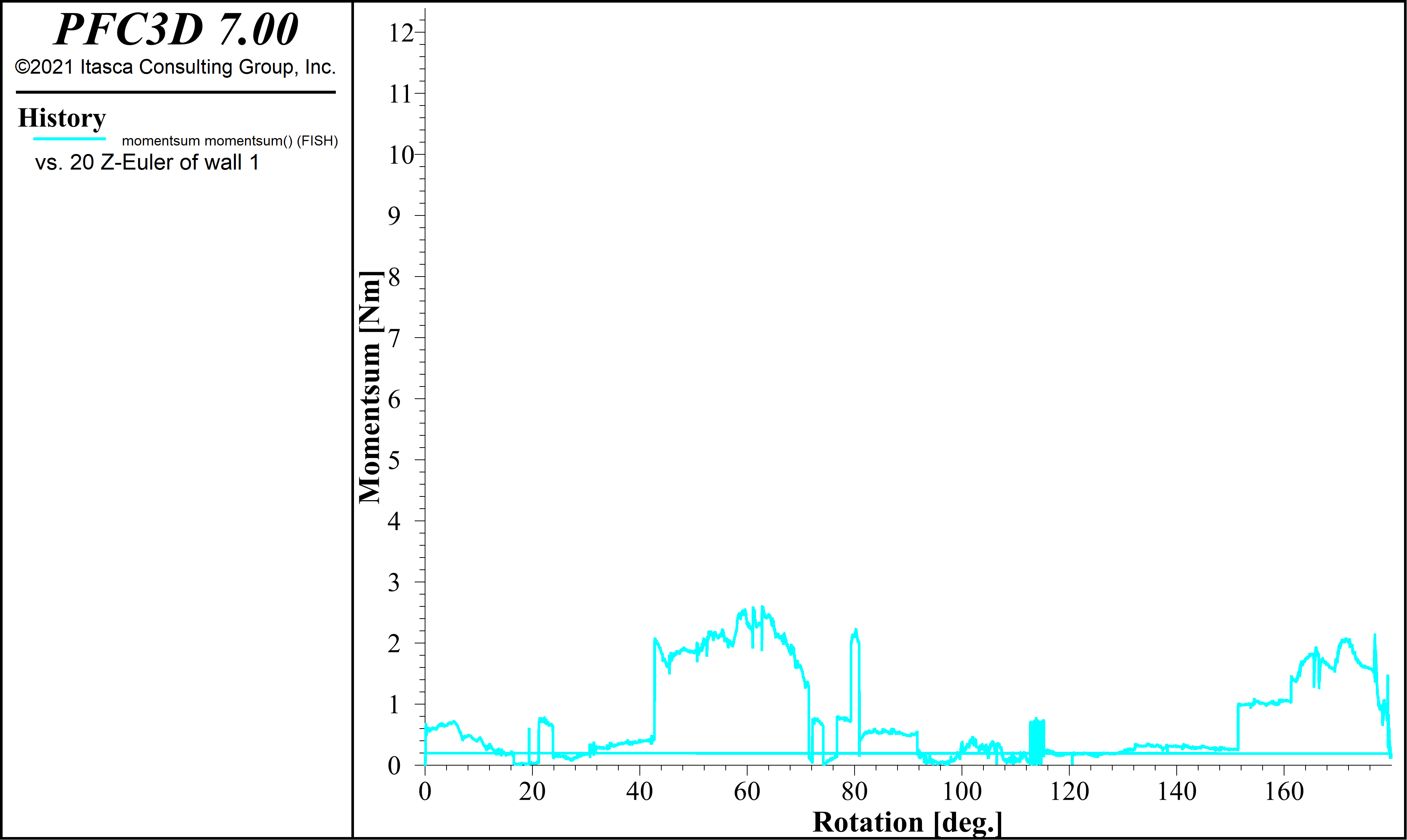
Fig 2: Moment calculated from the fish loops

Fig 3: Moment calculated wall.moment.contact.z command
As it can be observed, the moment from the loop is magnitudes smaller and shows an unrealistic trend in comparison to the values from the wall.moment.contact.z command. Could you please guide us on which method is to be followed? What are the differences in the two methods of determination?
Thank you again for the time and look forward to your reply.
Dear anjaliuday,
please send the inputfiles (and stl files) to software@itasca.de so that we can review it.
Regards,
Nils
Dear Mr. Ehringhausen,
Thank you. The files have been sent to the mentioned email.
Regards,
Anjali
Dear Anjali,
Sorry for the late response. It took us some time to figure the problem out. Please see the response below:
The FISH function defined as momentsum (provided below) had a few problems,

First, when calculating the moment in 3D you need to take into account all force components. The z-component of the contact force is normal to wall 6 (the wall in question), however, the balls are free to spin around the z-axis which will create a twisting moment on the wall in the z-direction. Therefore, it’s best to use the 3D definition of moment – F x d, where x is the cross-product.
Second, the distance (or moment arm) is calculated for the wall w.r.t it’s center of rotation. The center of rotation in this model changes during the compaction stage. You can modify the moment arm distance using wall.rotation.center().
Lastly, since you are using the Rolling Resistance Linear contact model, an additional moment is being applied to the wall if the rolling resistance friction is not zero. You can find out how the rolling resistance friction is calculated in the documentation - Rolling Resistance Linear Model — FLAC3D 7.0 documentation. This additional moment needs to be added when summing the moments.
Here is the modified FISH function I renamed to momentsum_edit (I’ve attached the data file as well),

You can see in the histories of the FISH functions momentsum_edit and momentztop, that the results match perfectly,

I hope that this is of help to you!
Regards,
Nils
editedFISH.dat (592 Bytes)
Dear Mr. Ehringhausen,
Thank you very much for your reply.
Regards,
Anjali
Hello,
I have the same model of the ring shear test. I created the upper and bottom platens with Autocad, however when i tried to import the with Wall import command i got thé message “no facets existes”. I notices alse that thé source didn’t go to thé specific file. Could any one help me with this
Regards,
DJAAFRI Djamel Eddine
Dear Djamedel,
I would suggest check the units of the AutoCAD and PFC model. Also create the plates at the origin, so that it would be easy to import. Hope this helps.
Regards,
Anjali
Dear Anjali,
I will try it.
Thanks.
Dear Anjaly,
Do i must use stl. file or dxf.file?
Regards,