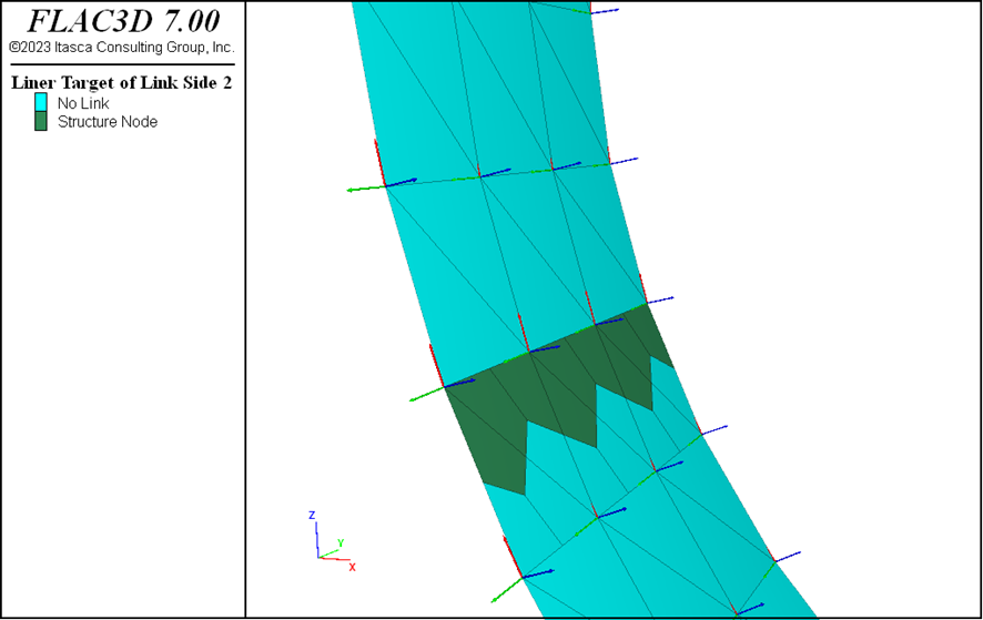
I try to model a circular tunnel with different liner IDs in one ring and the idea is to connect them with deformable links. My approach is to create links on side 2 to connect two liners with different IDs, while keeping the side 1 links connected to the zones. I apply these attach conditions on the joint:
structure link attach x normal-yield y shear-yield z shear-yield r-x free r-y normal-yield r-z free range group ‘JL’ slot ‘Joints’
However, using these conditions, I obtain asymmetric liner stress resultants at the location of the joint. For example the side of the source node having higher Ny then the side of the target node.
Do you mean that the liner elements are not symmetrical on both sides of the joint? My guess was using rigid links would yield similar results as using liner with single ID.
I tried to use cross-diagonal keyword while creating the liner. The distribution of the axial forces was neater. However, I obtained peaks of bending moments on the nodes that were not on the gridpoints, just as it is indicated in the Flac3D documentation.
The numerical values in the figure shared in the post are fairly similar on both sides. In the case of the bending moments, there happens to appear positive bending moments on one side of the joint and negative on the other, although the values are rather small.
However, do you have any recommendations on how to improve the smooth transition over the joint?