I’m trying to implementing a quite specific bilinear Mohr-Coulomb model. I consider my model to be specific in the way that the failure envelope is convex and not concave, ie. the friction angle of the second segment is larger than the friction angle of the first segment.
The failure envelope would look like this :
Unfortunately, when running the model, I’m under the impression that FLAC3D is systematically searching for the minimum between both linear failure criterias, which would be correct if the second segment had a lower friction angle. Ideally, I would have prefered FLAC3D to search for the intersection between both lines, and then apply the first segment on the left-hand side, and the second segment on the right-hand side.
Does anybody of you have experienced the same behaviour ?
And do you have any ideas on how to circumvent this drawback ?
The stress search methodology in FLAC3D can be described as follows:
Diagonal Line Assumption: Envision a diagonal line originating from the intersection corner that bisects the two existing lines.
Stress Correction Based on Position:
If the elastic trial stress is located to the left of this diagonal line, stress correction is applied to the left failure line.
Conversely, if the elastic trial stress is on the right, the correction is applied to the right failure line.
Simplification Using Distance: Instead of the above approach, we adopted a more straightforward criterion. By measuring the distance from the trial stress to both lines, we can determine its position. Mathematically, this method is equivalent to the combination of points (1) and (2).
Thank you for the reply.
But before searching the position left-right of the elastic trial stress, how does FLAC3D determine if it is failed or not ?
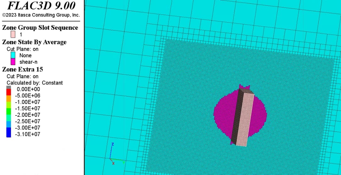
In the next figure, I indicated the position of one zone (the yellow star) just after a command model solve elastic only (in fact, there were several zones at that position around an excavated zone).
After doing a single step (not only elastic), all these zones became failed (shear now), even if they were below curve 1. And inversely, all zones that were below curve 2 remained intact.
So I thought that maybe FLAC3D was calculating the difference between the principal stress and the minimum between both curves in order to determine if the zone undergoes a plastic deformation or not. In cases where the friction angle of the second segment is lower than in the first segment, this approach would be working, because curve 1 would be below curve 2 in the first segment. But in my case, it is the opposite. This would explain why the zones at the yellow star are considered as failed : they are above curve 2.
Wait, is this a user-defined model? If yes, without the availability of specific codes, it’s difficult for us to pinpoint the problem. First you should determine the positive side for each yield curve and then take the above steps I proposed. It does not matter if the curve 2 is steeper or not than curve 1.
Note that in a plane the distance of a point to a line can be a negative value. Only a point is (1) in the positive side of a curve and (2) with the minimum distance to the same curve, then this curve controls the plastic stress correction. Take your above figure as an example, that point dose not meet the minimum distanced to curve 2 because it is with a negative distance to curve 1 and with a positive distance to curve 2. In this context, a negative distance is considered “more minimum” than a positive one.
I prepared a small test case to show exactly what I’m talking about. simple_model.dat (9.5 KB)
You can simply run this file.
At the end, some extras are filled. The most interesting are extra 14 and extra 15 :
extra 14 : a positive value indicates that the stress (in S1-S3 space) is above curve 1
extra 15 : a positive value indicates that the stress (in S1-S3 space) is above curve 2
If you plot plan and section views around the stope (center at (0,0,750.01)), you will see that extra_14 is negative everywhere, meaning that all zones are below curve 1.
If you plot extra_15, you will see several zones around the stope with a positive value, meaning that they are above curve 2.
Now, if you let the model do one single step (model step 1), and look at the plastic state of the zones around the stope, you will see that precisely all zones that had a positive extra_15 value (i.e. above curve 2, but below curve 1) are now failed. But they shouldn’t fail, because they are below curve 1…
Following an investigation, we judge that the root reason is that the physical nature of the model itself is instability:
This model contains octree zones with a considerable contrast in zone size. As a result, it demands a stricter criterion to be considered equilibrium. The existing commands:
zone relax excavate range group “1” slot “Sequence”
model solve and elastic only cycles 800
seem questionable. I’m uncertain about the reasoning behind using “elastic only” and the choice to use 800 cycles for equilibrium. We’ve modified these to:
zone relax excavate step 800 range group “1” slot “Sequence”
model solve ratio 1e-6 and cycles 801
Upon closer inspection of the excavation area, the vertical walls can be considered a slope angled at 90 degrees. Given its material properties, the “slope” cannot maintain stability. Even after running the model overnight, it still did not achieve equilibrium with ratio=1e-6.
With this understanding, it’s easier to know the SUBI behavior. Even if the current state is within the failure lines, the next step still includes a gravity load. This load can push the elastic trial stress outside the failure boundaries.
thanks again for considering my case. But I’m still not 100% sure on the SUBI behaviour with my convex bilinear Mohr-Coulomb properties.
If I’m running the script with your modifications in the relax excavate and solve commands, but with only the first curve (I’m just setting the parameters of the second segment equal to the first segment), then the model is solving to equilibrium (1533 steps). In fact, there are no failed zones.
But if I’m keeping my second segment, which corresponds to a stronger rockmass at higher confinement, the model is not solving to equilibrium. This doesn’t make sense to me.
In addition to that, I do agree with you that doing an elastic solve only for 800 steps does not make any sense. I did that only to highlight the correspondance between the zone above curve 2 but under curve 1, and those who fail after one single step.
The first picture below is taken after the solve elastic only command:
In grey are the zones whose stress state is under curve 1, but above curve 2 (just like the yellow star in the picture at the beginning of the discussion).
If I’m doing now a single solve step (model step 1) and look at the state of the zones, I get this :
Exactly those zones that were in grey have failed. So it might be an extraordinary coincidence, but I still think it is related to the fact that FLAC3D considers that the zone fails because it is above curve 2 (even if it shouldn’t because it is below curve1…).
Could you please consider again my case, especially my first remark (running the same code with only curve 1 works, while it doesn’t work with both curves even if the latter is a stronger rockmass).
Here S1 is the minimum principal stress, S3 is the maximum principal stress (note that S1 & S3 are positive in tension and negative in compression here). If the stress is above or on the solid lines, it is in plastic yielding. If the stress is below the solid lines, it is in elastic state. In the current SUBI model, whichever the lower line between f1 and f2 is the ultimate failure line.
Usually, f2 has lower friction angle so f2 is to the left of f1 as in Fig 1 in the doc. However, in your case, f2 is to the right of f1 because f2 has a higher friction angle in your case.
Below is the stresses after the first command of “model solve elastic ratio 1e-6” (or, before excavation):
We will see that some zones are at f2 line which implies that those zones are in shear failure to f2. However, again, these stresses will not in yielding to f1 if having only f1.
Your point might be: f2 is always to the left of f1. Then we need a new assumption that “f2 is always to the left of f1” rather than “whichever the lower line between f1 and f2 is the ultimate failure line”.
Thank you for the example. Upon further consideration, and to broaden the application of the SUBI model, we believe the assumption that “the f1 shear failure line always lies between the f2 failure line and the tension failure line” may be more appropriate. We will modify the algorithm so that the SUBI adheres to this rule, even when the failure surface is non-convex (rare case practically). This update is anticipated to be available starting from version v9.164. Using this new assumption, the failure line for your example would be:
This is really great news ! Looking forward the new release.
Do you think it would be too complex to broaden the SUBI to a trilinear Mohr-Coulomb model ?
The objective would be to implement a trilinear failure envelope as suggested by Kaiser :
Kaiser, P. & Diederichs, Mark & Martin, Derek & Sharp, J. & Steiner, Walter. (2000). Underground works in hard rock tunnelling and mining. Keynote lecture in proceedings of GeoEng2000, vol 1. Technomic Publishing Co. Lancaster. 841-926.
We’re unable to access the paper. Before making a decision, we need to review it. Could you please send a copy to flac3dsupport@itascacg.com? Thank you.